Principles of fluorescence spectroscopy (3) – Instrument configuration
October 6, 2020
Home / Principles / Principles of fluorescence spectroscopy (3) – Instrument configuration
Optical system
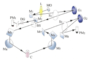
Figure 7 shows the typical configuration of a spectrofluorometer. The source light is introduced into an excitation monochromator, and monochromatic excitation light is produced by a diffraction grating and a slit. This is divided into an irradiation beam and a reference beam using a beam splitter. The reference beam is used to determine the excitation light intensity during detection and signal processing. In order to separate the fluorescence produced by the sample and the transmitted light, the fluorescence detector is placed at an angle of 90° to the incident light direction. To obtain a spectrum, the fluorescence is dispersed using a diffraction grating.
The fluorescence intensity is determined by dividing the value measured by the fluorescence detector by the reference light intensity. This is called the ratio calculation method, and it compensates for fluctuations of the light source and the wavelength characteristics of the excitation monochromator and light source.
Fig. 7 Optical configuration of spectrofluorometer
Light source
In a spectrofluorometer, a xenon lamp is usually used. It emits light by discharge of xenon gas and has a wide energy distribution from UV to infrared. However, the intensity decreases in the UV region of 300 nm or less, but a bright line exists near 450 nm.
Fluorescence measurement cell
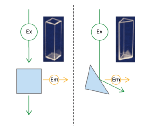
Fluorescence is detected at an angle of 90° with respect to the excitation light direction. Therefore, a four-sided transmission cell is used. When the sample solution is concentrated, the excitation light cannot penetrate the cell, so surface fluorescence is measured using a triangular cell. In this case, the incidence angle is set to 60°, for example, to prevent excitation light reflected at the cell surface from entering the detector. Cells can be made of glass or quartz. Glass is inexpensive but does not transmit light below 330 nm, and is not suitable for use with samples that require UV excitation.
Fig. 8 Four-sided transparent cell (left) and triangular cell (right)