6. Signal Processor
As shown in Figure 14, the CPL spectrometer captures both the AC (ΔI) and DC (IA) components of the signal. These values are used to calculate the degree of ellipticity (θ), which is the vertical axis when plotting CPL data. This allows CPL to be represented based on the same definition as the ellipticity commonly used in CD measurements.
Let EL and ER represent the electric field amplitudes for LCP and RCP light, respectively. Assuming that the luminescence is propagating directly towards the detector and EL > ER, the combined electric field vectors form an elliptical polarization pattern (Figure 15). The minor axis amplitude (x-direction) is ER – EL , and the major axis amplitude (y-direction) is ER + EL. The ellipticity angle θ is defined as the angle between the major and minor axis vectors relative to the origin.
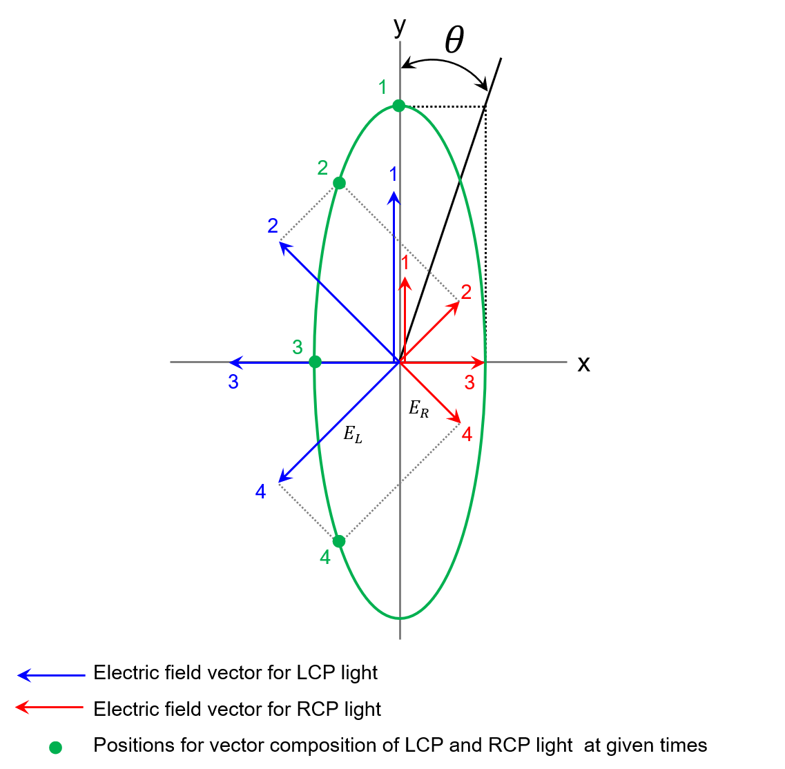
Fig. 15 Relationship between electric field vector and degree of ellipticity for LCP and RCP light
The relationship between EL, ER and θ is expressed by:

Since the relationship between the light intensity I and the amplitude E of the electric field vector is expressed as

Equation (2) can be rewritten as:

Multiplying both sides of Equation (4) by (√(IL)+√(IR)) finally yields:

Since the difference between IL and IR is negligibly small, it can be assumed that IL≈IR≈IA. Therefore,

is obtained. Next, the units for the degree of ellipticity are converted from radians to millidegrees. Since θrad is very small, the following equation holds:

By substituting Equation (7) into Equation (6), the following equation is obtained:

In actual CPL measurements, the raw data obtained are θmdeg or θmdeg‘, together with DC, which are related by the following equation.

For the CPL-300, a (1S)-(+)-10-ammonium camphorsulfonate aqueous solution is used to calibrate the vertical axis (θmdeg). The CD value at 290.5 nm for a 0.06% (w/v) aqueous solution of this substance is known to be +190.4 millidegrees for an optical path length of 10 mm, and this is used as the scale standard for CD spectrometers. This solution is placed in the sample compartment, and both the excitation and emission wavelengths are set to 290.5 nm. Since the difference between the transmitted LCP and RCP light intensity due to the circular dichroism exhibited by the sample is accurately known, this is used to calibrate the instrument, as described in detail below. The CD value for the (1S)-(+)-10-ammonium camphorsulfonate aqueous solution is +190.4 millidegrees, indicating that absorption of LCP light is larger than that of RCP light, so that the transmitted RCP light intensity is higher than the transmitted LCP light intensity. Assuming that the circularly polarized component of the transmitted light can be regarded as CPL, the fluorescence intensity is higher for RCP light as in the case of transmitted light. Therefore, when the (1S)-(+)-10-ammonium camphorsulfonate aqueous solution is measured using CPL spectroscopy, the signal is negative and the intensity is −190.4 millidegrees.
When converting the vertical axis units from θmdeg‘ to ΔI, the following equation, which is based on Equations (8) and (9), is used:

The vertical axis units are converted from θmdeg‘ to ΔI using:

Related Posts:
 properties of platinum complexes using a CPL measurement system and a spectrofluorometer") Evaluation of aggregation-induced circularly…
Evaluation of aggregation-induced circularly… Base Material and Dye Analysis - Combined Raman and…
 Highly efficient spectral measurement methods using…
 Combined Analysis of Thermochromic Materials -FT-IR…
 Vibrational Circular Dichroism Spectrometer based on…
 Evaluation of Degree of curing for Epoxy Resins…