Introduction
Dielectric multilayer mirrors are laminated optics comprising of a combination of high refractive index and low refractive index materials. Using the interference effect, this mirror can provide extremely high reflectance (near 100%) in a specific wavelength range (Figure 1). Since these mirrors are widely used in cameras, telescopes, and optical communications devices to reduce the loss in light intensity, it is important to evaluate the material’s reflectance with very high accuracy.
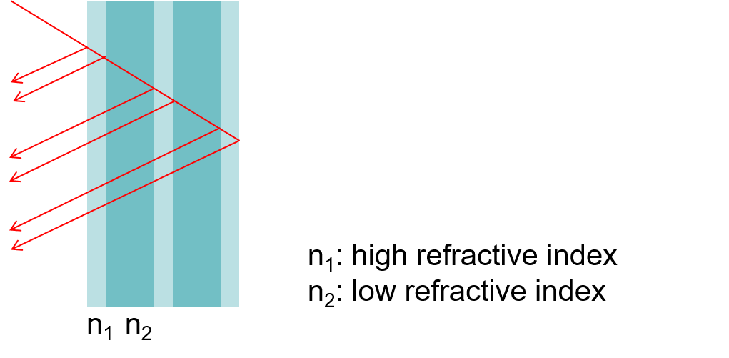
Figure 1. Schematic of the dielectric multilayer mirror
The absolute reflectance measurement system and the V-700 Series UV-Visible spectrophotometer provide high photometric stability for accurate measurements. The absolute reflectance system can perform measurements at arbitrary and user-selected incident angles, allowing the measurement of dielectric multilayer mirrors at specific incident angles.
This article demonstrates the use absolute reflectance measurement system for obtaining highly reflective measurements for a dielectric multilayer mirror.
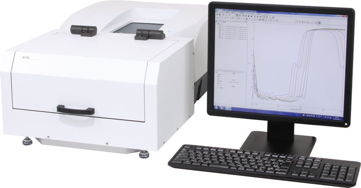
Absolute reflectance measurement system
Experimental
A dark measurement was performed with a light-shielding plate, the baseline measurement was performed against air, and then the sample measurement obtained. This procedure was repeated three times at the conditions listed below.
Measurement condition
Bandwidth: 5 nm
Response Time: 3.84 seconds
Data Interval: 1 nm
Scan Speed: 20 nm/min
Incident Angle: 10°
Polarization: p-polarized light
Keywords
UV-Visible/NIR, Absolute reflectance, dielectric materials
Results
Figure 2 shows an overlay of the absolute reflectance of the dielectric multilayer mirror and Figure 3 is a zoomed in view of the same spectra. The measurement repeatability of the system is very high and Table 1 compares the theoretical and measured reflectance values. The difference between the measurement average reflectance value and the theoretical value is greater than 0.15%, indicating that the absolute reflectance system has high accuracy and good correlation for reflectance measurements close to 100%R.
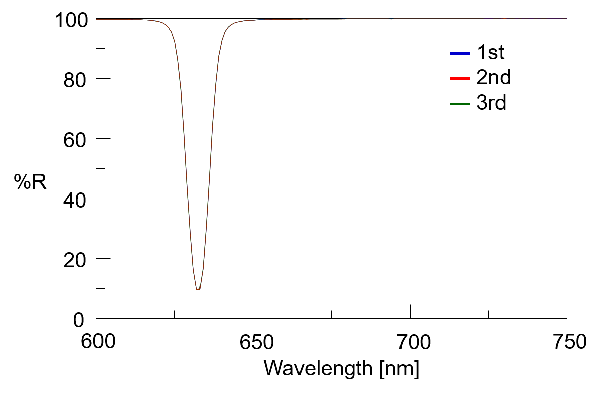
Figure 2. Absolute reflectance spectra of the dielectric multilayer mirror
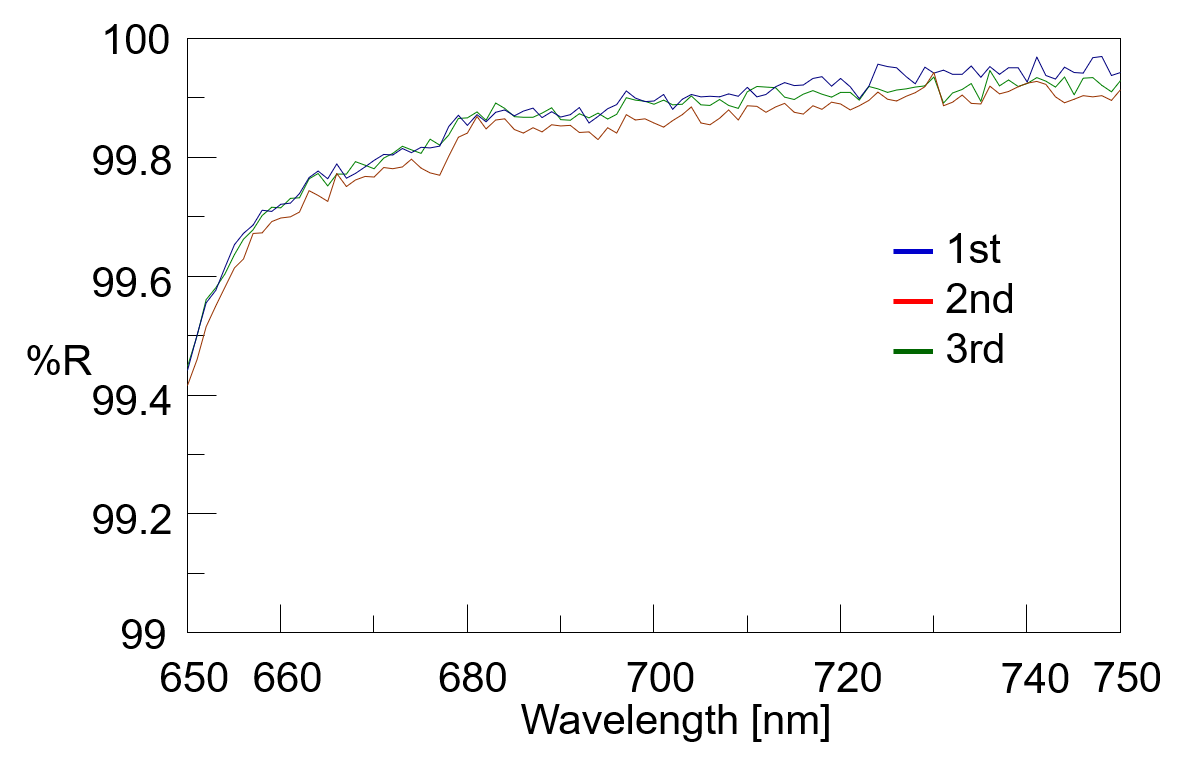
Figure 3. Absolute reflectance spectra of the dielectric multilayer mirror (~100%R)
Table 1. Comparison of theoretical and measured reflectance values
| Wavelength | Expected Value %R | Measurement Value %R | Average %R | Standard Variation | Variation Coeffecient % | Difference Between Expected and Average | ||
| 1 | 2 | 3 | ||||||
| 680 | 99.9914 | 99.8663 | 99.8537 | 99.8407 | 99.8536 | 0.013 | 0.013 | -0.1378 |
| 700 | 99.9918 | 99.8892 | 99.8943 | 99.8578 | 99.8804 | 0.020 | 0.020 | -0.1114 |
| 720 | 99.9839 | 99.9094 | 99.9316 | 99.8889 | 99.9100 | 0.021 | 0.021 | -0.0739 |
Related Posts:
 Evaluation of Spectral Characteristics of Dichroic…
 Determination of Absolute Configuration of Molecules…
 Evaluation of Reflectance of Microlens Surface using…
 Base Material and Dye Analysis - Combined Raman and…
 Highly efficient spectral measurement methods using…
 Analysis of CBN-Binding DNA Aptamer using CD Spectroscopy") Higher-Order Structure (HOS) Analysis of CBN-Binding…
Higher-Order Structure (HOS) Analysis of CBN-Binding…