Introduction
Key Points
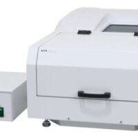
Using the CPL-300 circularly polarized luminescence measurement system and a dedicated accessory, the magnetic circularly polarized electroluminescence (MCPEL) spectrum of magnetic circularly polarized organic light emitting diodes (MCP-OLEDs) can be measured.
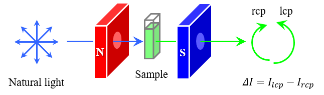
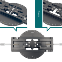
CP-OLED devices that emit circularly polarized luminescence have potential applications in devices such as 3D displays and lights for plant growth, and extensive research into this phenomenon has been conducted in recent years.1) A typical method for generating circularly polarized luminescence from a device is to use optically active molecules for the light-emitting layer. However, Imai et al. succeeded in developing a CP-OLED device capable of generating circularly polarized luminescence (CPL) even when using optically inactive molecules, by applying a magnetic field to the device.2) In the present study, the MCPEL properties of such devices are evaluated using a CPL measurement system with a dedicated accessory that allows measurements to be performed while simultaneously applying a voltage and a magnetic field to the device. This accessory allows easy adjustment of the optical axis and simple electrode wiring (Figure 1). In this report, we describe the evaluation results for four MCP-OLEDs with different optically inactive iridium complexes as the light-emitting layer, that emit in the red, green, blue, and yellow regions.
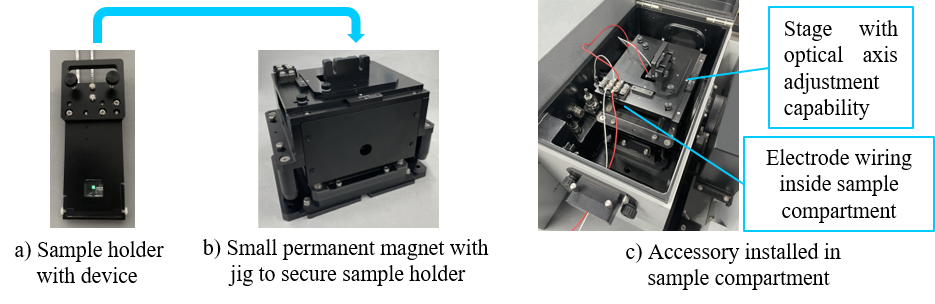
Fig. 1 External view of dedicated MCP-OLED accessory
Experimental
Sample
MCP-OLED devices with Ir(piq)3, Ir(ppy)3, Ir(F2–ppy)2(pic), or Ir(BT)2(acac) (Figure 2) as emitting layer (Light-emitting area: 2 mm x 2 mm)
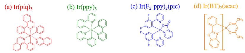
Fig. 2 Structure of iridium complexes
System
Instrument: CPL-300 CPL measurement system
Accessory: PMCD-586 Compact permanent magnet
Dedicated MCP-OLED accessory*
Software: Spectra measurement program
* This product is a custom-ordered item.
Parameters
Em. Bandwidth: 10 nm
Scanning speed: 100 nm/min
Response: 4 s
Data interval: 0.5 nm
Accumulations: 2
Magnet field: 1.7 T
Keywords
MCP-OLED, CP-OLED, MCPEL, CPEL, MCPL, CPL, Magnetic circularly polarized luminescence, Circularly polarized luminescence, Device
Results
Figure 3 shows photographs of the devices under an applied voltage of 8 V, where each device emits strong red, green, blue or yellow luminescence. The corresponding MCPEL and EL spectra are shown in Figure 4, under a magnetic field of ±1.7 T. A clear EL signal is seen in each wavelength region. In the case of a magnetic field of +1.7 T (N-up), Ir(piq)3 and Ir(ppy)3 exhibit negative MCPEL signals, while Ir(F2-ppy)2(pic) and Ir(BT)2(acac) exhibit positive MCPEL signals. These signals are reversed under a magnetic field of -1.7 T (S-up), confirming that mirror-image MCPEL spectra can be obtained by reversing the direction of the applied magnetic field.

Fig. 3 Photographs of light-emitting surfaces
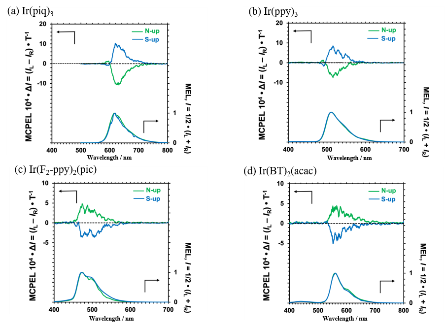
Fig. 4 CPEL and EL spectra of iridium complexes
Conclusion
MCPEL and EL spectra were measured for MCP-OLEDs with four types of optically inactive iridium complexes as the emitting layer, using a dedicated accessory. This accessory allows easy alignment of the optical axis of the device and simplifies electrode wiring, so that stable MCPEL measurements can be performed.
MCP-OLED technology is expected to be applied to next-generation display devices, including 3D displays.
References
1.D.-W. Zhang, M. Li, C.-F. Chen: Chem. Soc. Rev., 49, 1331 (2020). DOI: 10.1039/C9CS00680J
2.K. Hara, A. Morimoto, K. Matsudaira, S. Suzuki, S. Yagi, M. Fujiki, Y. Imai: ChemPhotoChem., 6, e202100253(2022). DOI: 10.1002/cptc.202100253
3.M. Kitahara, K. Hara, S. Suzuki, H. Iwasaki, S. Yagi, Y. Imai: Org. Electron., 119, 106814 (2023). DOI: 10.1016/j.orgel.2023.106814
Acknowledgements
This work was performed under the guidance of Prof. Yoshitane Imai, Faculty of Science and Engineering, Kindai University.